1. Overview
The BunHMI Display is a Human-Machine Interface (HMI) solution that leverages LVGL and integrates an onboard GUI processor and memory with a touch display.
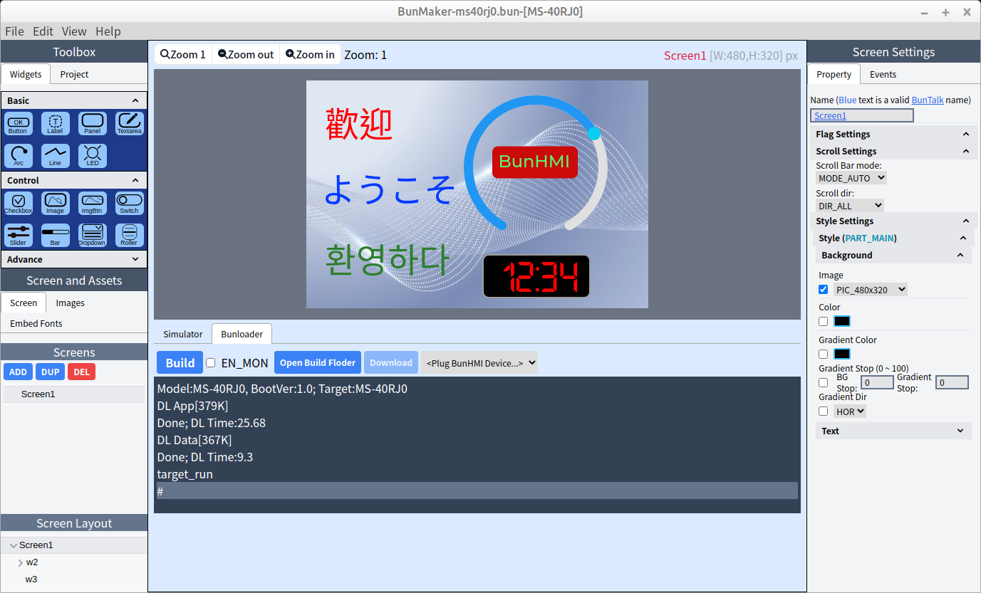
Additionally, we provide the free BunMaker software for rapid GUI project development, enabling you to design HMIs as effortlessly as cooking delicious buns—quickly, easily, and with variety.
2. BunHMI
The BunHMI features two major sockets on its bottom side: a UART socket and a Type-C socket, as shown in Figure 2.
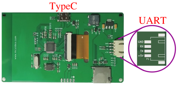
The Type-C socket is used to download firmware via BunMaker (Figure 1).
The UART socket connects to the host (MCU) and includes the following four pins:
-
+5V: +5V power supply
-
TX: BunHMI UART Tx signal with a logical level of 3.3V
-
RX: BunHMI UART Rx signal with a logical level of 3.3V
-
GND: Ground
The default UART baud rate is 115200, 8n1.
|
Warning
|
The voltage level of the BunHMI UART is 3.3V. It is compatible with 5V TTL interface devices but not with 5V CMOS devices. |
|
Warning
|
Do not connect the BunHMI to an RS-232 interface. Doing so will cause irreparable damage to the BunHMI display. |
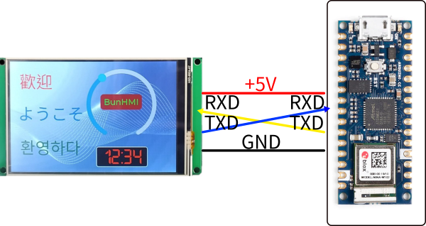
Figure 3 illustrates a typical connection diagram between the BunHMI and an Arduino device.
2.1. Boot Modes
The BunHMI supports two boot modes:
-
Download Mode: When the Type-C cable is connected, the BunHMI enters download mode, allowing firmware to be downloaded using BunMaker (Figure 1).
-
Normal Mode: When the UART cable is connected and powered by +5V, the BunHMI boots into normal mode and runs the GUI firmware.
2.2. SD Card
The BunHMI includes an SD card socket on its bottom side. It supports the FAT32 filesystem. Using Buntalk, you can display image files from the SD card, play WAV files, and read or write strings to files on the SD card for data logging purposes.
For more details about SD card access, please refer to the BunTalk documentation.